How do you make custom VASI/PAPI lights??


Vasi/Papi Lights
Started by
Ubeans2001
, Dec 29 2006 03:21 AM
13 replies to this topic
#1
Ubeans2001
-
- Members
-

- 640 posts
Private Pilot - IFR
- Location:Las Vegas, Nevada
Posted 29 December 2006 - 03:21 AM
#2
TechnicolorYawn
-

- Members
-
- 8,581 posts
Orville Reincarnate
- Location:Manchester, UK(EGCC)
Posted 29 December 2006 - 12:16 PM
Its pretty complicated and involves tweaking the code produced by Gmax to make light objects only appear in certain situations.
However you can get results like this:

First you need to change the way Gmax exports objects. Do you have it set up so you can tweak the .asm and _0.asm files?
However you can get results like this:
First you need to change the way Gmax exports objects. Do you have it set up so you can tweak the .asm and _0.asm files?
Edited by TechnicolorYawn, 29 December 2006 - 12:17 PM.
#3
Ubeans2001
-
- Members
-
- 640 posts
Private Pilot - IFR
- Location:Las Vegas, Nevada
Posted 29 December 2006 - 03:04 PM
If you mean the Keep=1 thing then yes I do.
#4
Ubeans2001
-
- Members
-
- 640 posts
Private Pilot - IFR
- Location:Las Vegas, Nevada
Posted 02 January 2007 - 09:50 AM
I have all the setting and I made a PAPI model already so I'm ready!! Hope you reply to this TCY. You always seem to have the solution. 
#5
Ubeans2001
-
- Members
-
- 640 posts
Private Pilot - IFR
- Location:Las Vegas, Nevada
Posted 04 January 2007 - 10:26 AM
Waiting..........Waiting..........Waiting..........Waiting..........Waiting..........Waiting..........
Waiting..........Waiting..........Waiting..........Waiting..........Waiting..........Waiting..........
Waiting..........Waiting..........Waiting..........Waiting..........Waiting..........Waiting..........
Waiting..........Waiting..........Waiting..........Waiting..........Waiting..........Waiting..........
Waiting..........Waiting..........OK TCY I'm ready...........Waiting..........Waiting..........
Waiting..........uhhhhhhhh.
Waiting..........Waiting..........Waiting..........Waiting..........Waiting..........Waiting..........
Waiting..........Waiting..........Waiting..........Waiting..........Waiting..........Waiting..........
Waiting..........Waiting..........Waiting..........Waiting..........Waiting..........Waiting..........
Waiting..........Waiting..........OK TCY I'm ready...........Waiting..........Waiting..........
Waiting..........uhhhhhhhh.
Edited by Ubeans2001, 04 January 2007 - 10:27 AM.
#6
TechnicolorYawn
-
- Members
-
- 8,581 posts
Orville Reincarnate
- Location:Manchester, UK(EGCC)
Posted 05 January 2007 - 08:45 AM

OK, first you need to create your PAPI box in Gmax. I'll leave it up to you how you make this. The important part however is the light object. In front of where you have the bulbs, create a *tiny* box for each lightbulb and place it just in front of each bulb. Then create 2 materials - one should be called LIGHT_NAV_red and the other LIGHT_NAV_white. These names are important as adding 'LIGHT_NAV_' to the material name will make MakeMDL export that object as a light effect instead of a 3D object. Don't apply any textures to these materials - instead click the colour block next to 'diffuse' and set the white material to white and the red material to red. Then apply each material to the box in front of the appropriate light.
You should end up with something like this (yours will be textured of course
):
Now you need to select just the PAPI box and export it as one object (called papiBox or something), then select just the light boxes and export them 4 times as different objects(as papiLights1, papiLights2 etc).
Now comes the tricky part. We need to edit the asm files that have been produced by MakeMDL in order to change the behaviour of the lights. Open the papiLight _0.asm files and in each one (if you've made the light materials correctly) you'll find a chunk of code saying:
papiLights_MasterScale_1 label BGLCODE

    IFMSK       nolgt_1, dict_0_g_lightStates, LIGHT_NAV_MASK
    BGL_LIGHT LIGHT_NAV, -12.528, 74.697, 45.422, 20, 0.60, 0.40, 0FFFFFFFFh, 0.000000, 0.000000, 1.000000; source poly num = 1
    nolgt_1       label BGLCODE

    IFMSK       nolgt_2, dict_0_g_lightStates, LIGHT_NAV_MASK
    BGL_LIGHT LIGHT_NAV, 15.558, 74.697, 45.422, 20, 0.60, 0.40, 0FFFF0000h, 0.000000, 0.000000, 1.000000; source poly num = 2
    nolgt_2       label BGLCODE
    BGL_RETURN
This is the part that defines the light, but it needs a bit of tweaking before it will work properly. Delete the two lines that start 'IFMSK..' and the two lines that start 'nolgt_1' and 'nolgt_2' as we don't need them. and above the first BGL_LIGHT line add 'BGL_ZBIAS 1' - this will stop the PAPI box blotting out the light effects at a distance.
Your chunk of code should now read:
papiLights_MasterScale_1 label BGLCODE

BGL_ZBIAS 1

    BGL_LIGHT LIGHT_NAV, -12.528, 74.697, 45.422, 20, 0.60, 0.40, 0FFFFFFFFh, 0.000000, 0.000000, 1.000000; source poly num = 1

    BGL_LIGHT LIGHT_NAV, 15.558, 74.697, 45.422, 20, 0.60, 0.40, 0FFFF0000h, 0.000000, 0.000000, 1.000000; source poly num = 2

    BGL_RETURN
If you were to export this now and place it in FS, you'd get a red light and a white light that are on constantly. Now we need to add conditions so that the lights only show up when the situation is appropriate.
We need to use something called a 'separation plane'. Think of this a big flat invisible rectangle placed in space. If you are on one side of the rectangle the light is turned on, and if you are on the other side, it is turned off.
This is the code I've used for one of my PAPI boxes. I'll explain each line below.
papilight3_MasterScale_1 label BGLCODE

BGL_ZBIAS 5

SEPARATION_PLANE noPapi, 22074, 0, 24217, 32768

    SEPARATION_PLANE below, -1338, 32718, -1217, 32768
    BGL_LIGHT LIGHT_NAV, 7.909, 19.345, 2.514, 20, 0.60, 0.40, 0FFFFFFFFh, 0.000000, 0.000000, 1.000000; source poly num = 1
    BGL_JUMP_32 above
	below label BGLCODE


    BGL_LIGHT LIGHT_NAV, 7.909, 19.345, -1.906, 20, 0.60, 0.40, 0FFFF0000h, 0.000000, 0.000000, 1.000000; source poly num = 2
    above label BGLCODE
    noPapi label BGLCODE
    BGL_RETURN
'SEPARATION_PLANE noPapi, 22074, 0, 24217, 32768' - This is the code for a separation plane. The word 'nopapi' is a marker showing where to jump to in the code if the condition fails (ie, if you are on the wrong side of the invisible rectangle). If you look further down there is a line saying 'noPapi label BGLCODE' - Here is where the process will jump to if the condition fails, otherwise it will execute the lines directly below it. The numbers after this marker define where the separation plane sits in space and at what angle. This first separation plane checks if you are in front of the PAPI box. If you are behind it, it skips the lines that define the lights, so they don't appear.
'SEPARATION_PLANE below, -1338, 32718, -1217, 32768' - This second separation plane checks if you are above or below the glidepath angle. You can see that if the condition fails, the process will jump to the line 'below label BGLCODE' and carry on to execute the code for the red light, and if it passes, it will execute the code for the white light. The line 'BGL_JUMP_32 above' below that makes the process then jump to the line 'above label BGLCODE' - if the white light code is executed, then it skips out the code for the red light.
You should make your code look like this, however the lines which define the actual lights and the 'ZBIAS' line you should leave alone.
Now you need to work out the coordinates of the separation planes you should use. Think of the separation plane as I said, as a big floating rectangle in space - if you are on one side the condition is met, if you are on the other side, the condition fails. Now think of this rectangle as having a long line poking out of its centre at right angles to the surface. The bottom of this line, where it meets the rectangle is at coordinates (0,0,0) the coordinates for the top of the line are the coodinates you use when you define the separation plane. Its possible to work this out with a pen and paper, but you can use Gmax to help you here.
In Gmax, create a flat square big enough so you can see it properly, with its coords at (0,0,0). Now create a line that points vertically upwards and is exactly 32768 metres long. Place this line on top of the rectangle so the bottom point is at (0,0,0) and the top is at (0,0,32768). You can move specific points by selecting the line, clicking the modify tab
 and going into vertex mode
It should look like this:

Now join the line to the rectangle by selecting the line and clicking the link button
 then dragging from the line to the rectangle. This will link them together so that when the rectangle moves, the line moves with it.
Looking at this picture here http://img441.images...pianglesqp1.gif shows the angles at which each PAPI light should change. We'll use the bottom one for now which is set at an angle of 2* 30' or 2.5 degrees. So we rotate our rectangle by 2.5 degrees. Now you need to work out what direction your PAPIs will point. Separation planes do not rotate with the object when you place it, so whatever value you have in 'heading' in the XML you use to place the object you'll need to rotate the separation plane by the same amount. Just rotate the rectangle about its Z axis unti, its pointing the right direction.
Now select the line and once more click the modify tab, go into vertex mode and select the top point of the line then select the Move button. Hit F12 to bring up the coords of that point and note them down. These will be the coords you use in the separation plane lines. The only difference is that in Gmax the coordas are in the order X,Y,Z, in the separation plane line they go Y,Z,X so you'll have to move them around appropriately. The last number is used to move the centre of the plane forwards and backwards, but we don't need to do this. It will always be 32768 for our purposes.
Now you can go ahead and calculate the coords for each separation plane for each light (rememeber the first separation plane checks if you are in front of or behind the PAPI box, so the plane will be on its side with the line parallel to the ground).
Once you've finished, recompile all your light files into mdls. You should now have mdls for the PAPI box itself and four sets of lights, each reacting to slightly different angles. Now itys just a case of making an XML file that places four PAPI boxes and at exactly the same coords a set of the appropriately angled lights.
If it works first time you're a better man than me...

The best of luck to you.
#7
PiP
-
- Members
-
- 14,896 posts
Cruising at FL140
- Location:Windermere, GB. EGNL
Posted 05 January 2007 - 12:55 PM
Nice, you can also choose from a whole bunch of different systems in AFCAD.
#8
TechnicolorYawn
-
- Members
-
- 8,581 posts
Orville Reincarnate
- Location:Manchester, UK(EGCC)
Posted 05 January 2007 - 01:47 PM
Heh.. yeah - AFCAD makes the whole thing MUCH easier
But you can't make actual PAPI boxes and if you're using groundpolys the AFCAD PAPIs won't show.
But you can't make actual PAPI boxes and if you're using groundpolys the AFCAD PAPIs won't show.
#9
Ubeans2001
-
- Members
-
- 640 posts
Private Pilot - IFR
- Location:Las Vegas, Nevada
Posted 10 January 2007 - 01:08 PM
Well....I did what you said and it actually came out better than I thought....I messed up somewhere so I'm currently trying to find where I messed up.
#10
Mark1
-

- Members
-
- 3,748 posts
Airline Transport Pilot
- Location:UK
Posted 10 January 2007 - 01:25 PM
Looks good Ubeans
Which part are you referring to when you say "messed up" Is it the box getting in the way of the lights?
Which part are you referring to when you say "messed up"
Is it the box getting in the way of the lights?
#11
mobisone
-

- Members
-
- 1,934 posts
Commercial Pilot
- Location:ALASKA
Posted 10 January 2007 - 01:39 PM
i would like to see what they look like from the proper perspective
>> the GLIDESCOPE PATH <<
>> the GLIDESCOPE PATH <<
#12
Ubeans2001
-
- Members
-
- 640 posts
Private Pilot - IFR
- Location:Las Vegas, Nevada
Posted 10 January 2007 - 03:00 PM
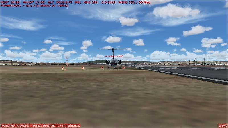
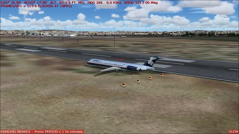
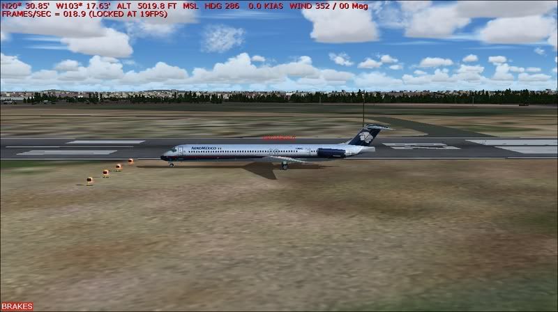
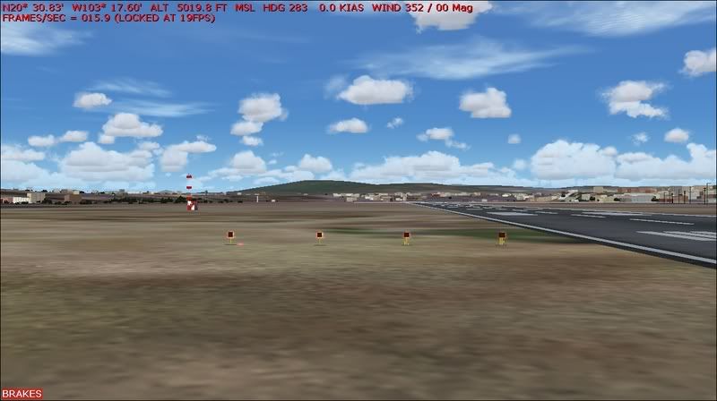
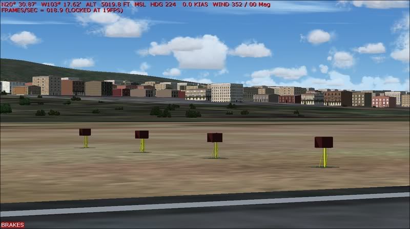
Here is a screenshot of the glideslope path as requested:
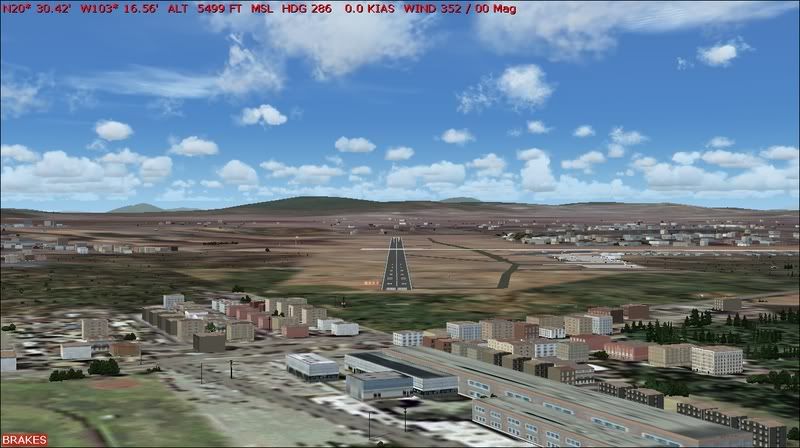
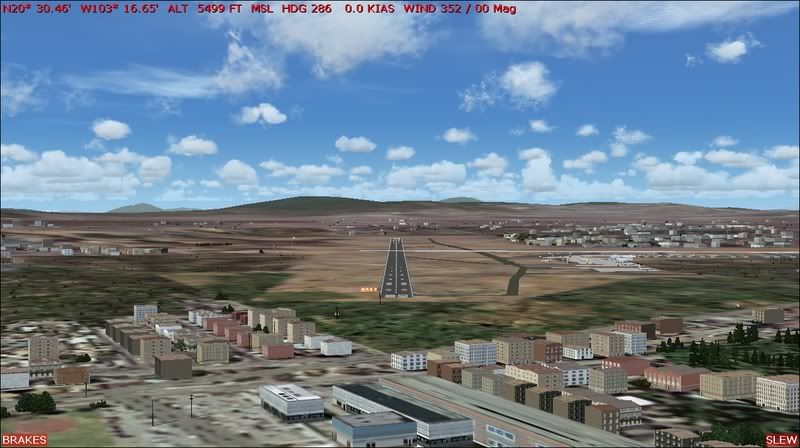
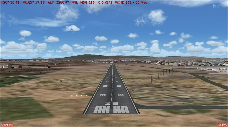
This one was taken after a texture reload...Notice the VASI lights are gone!!!
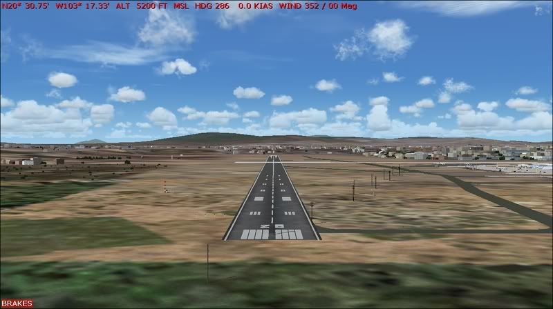
And when I would approach the runway all the lights would be red...then when I would pass the runway all of them would turn white....And I know the utility lines are in the middle of the runway..Ground 2K4 did that so I have to fix that.....
This one was taken after a texture reload...Notice the VASI lights are gone!!!
And when I would approach the runway all the lights would be red...then when I would pass the runway all of them would turn white....And I know the utility lines are in the middle of the runway..Ground 2K4 did that so I have to fix that.....
Edited by Ubeans2001, 10 January 2007 - 03:01 PM.
#13
wyoairbus
-

- Members
-
- 6,283 posts
Orville Reincarnate
- Location:Cheyenne, Wyoming US
Posted 10 January 2007 - 06:06 PM
Ubeans2001, on Jan 10 2007, 03:00 PM, said:
And when I would approach the runway all the lights would be red...then when I would pass the runway all of them would turn white....And I know the utility lines are in the middle of the runway..Ground 2K4 did that so I have to fix that.....

Unless you stayed underneath the glide slope, that is what would happen, and I don't think the placement of the lights would matter, or is the glide slope made along with the placement of the lights? Sorry i don't know much about modeling,
just my $.02
Edited by wyoairbus, 10 January 2007 - 06:08 PM.
#14
Ubeans2001
-
- Members
-
- 640 posts
Private Pilot - IFR
- Location:Las Vegas, Nevada
Posted 12 January 2007 - 06:47 PM
No it wasn't that..I was slewing at one altitude and the VASI wasn't doing anything.


